

To use esp32-board first, we need to select the ide that allows us, to write programs in esp32-boards so, the ide that we use for this blog will be Arduino-ide
For instruction to install esp32-board with Arduino-ide click the below link
Esp32 pins
Esp32 contains 15 pins on the left side of the board, and 15 pins on the right side of the board so, that means esp32 will have 30 pins

Simple sketch to blink a Led
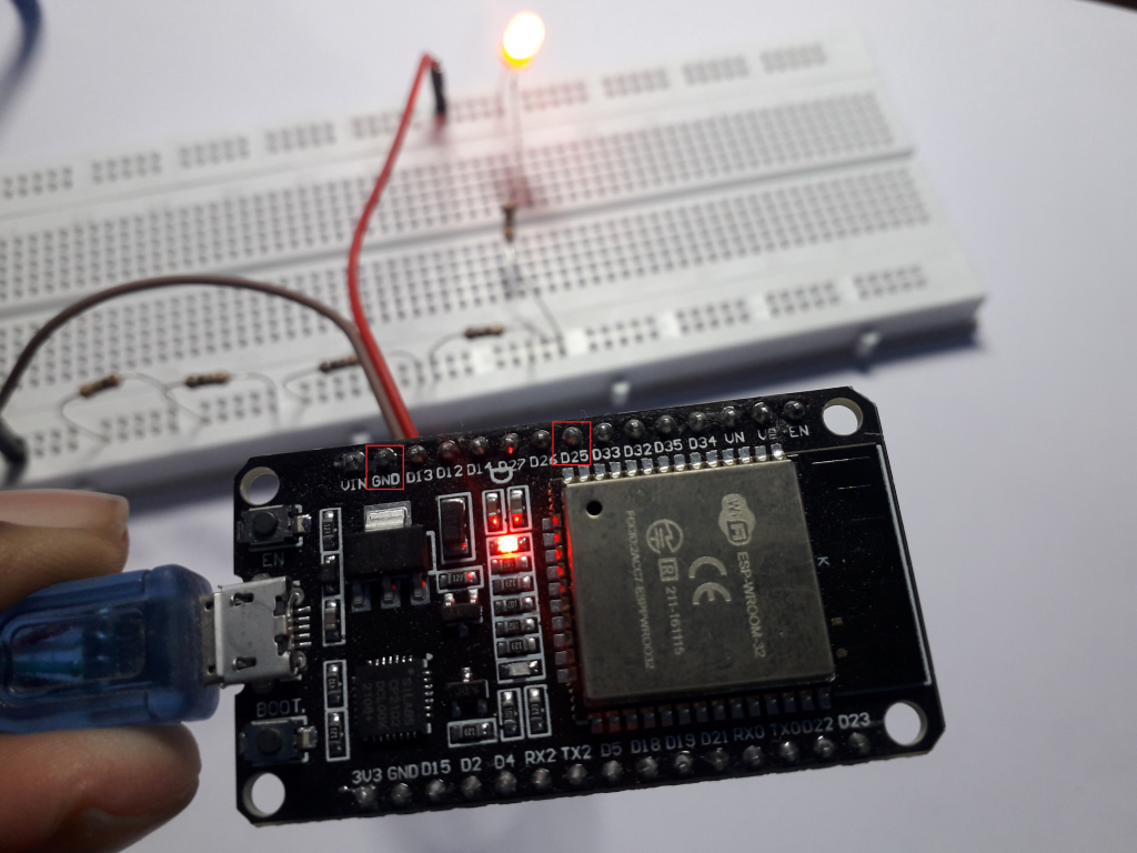
To blink an external led with esp32 we need to connect the GND pin of esp32 with breadboard GND and according to the sketch connect esp32 pin D25 to the positive(+) pin of the led
it is the same process, that we use with the Arduino board but the difference is that we use jumper wires of male to female instead of male to male
const int ledPin = 25;
void setup() {
  // initialize digital ledPin as an output.
  pinMode(ledPin, OUTPUT);
}
// the loop function runs over and over again forever
void loop() {
  digitalWrite(ledPin, HIGH);   // turn the LED on (HIGH is the voltage level)
  delay(1000);                       // wait for a second
  digitalWrite(ledPin, LOW);    // turn the LED off by making the voltage LOW
  delay(1000);                       // wait for a second
}
ON and OFF a LED with the push button
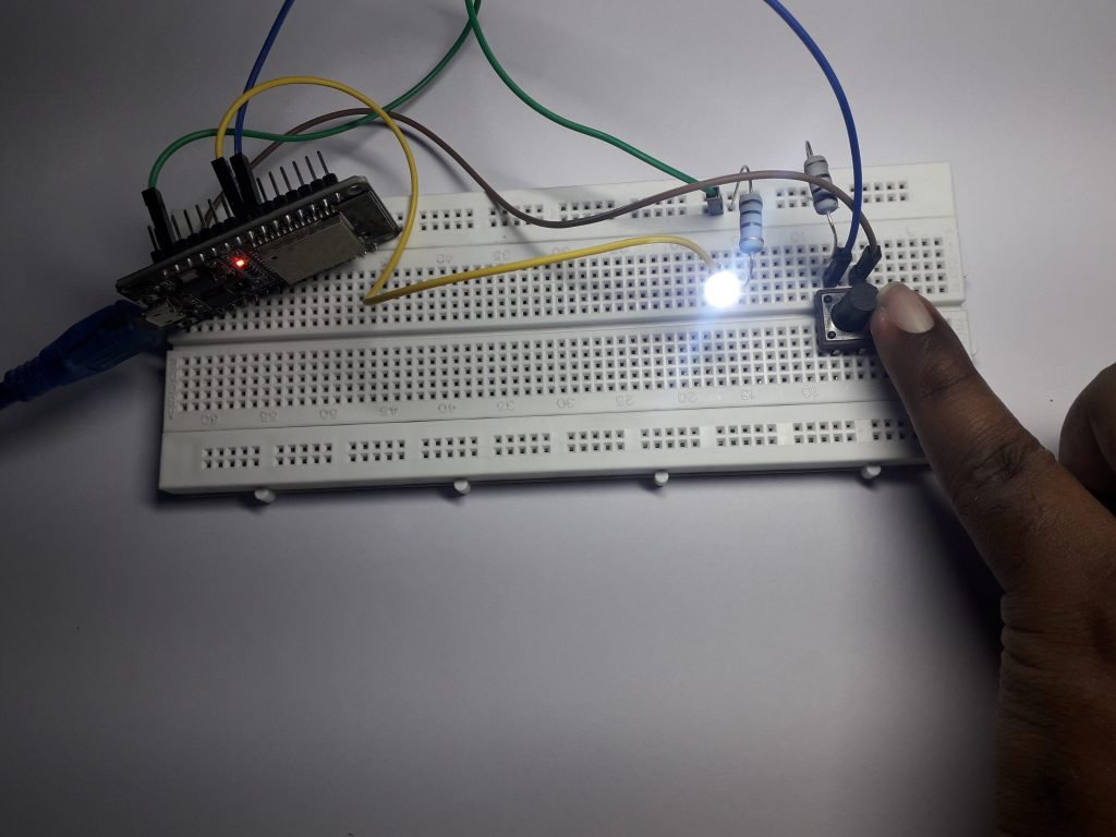
First, insert a push button into a breadboard
Second, connect esp32 3V3 pin with one pin of push-button
Third, connect another pin of push-button with a resistor that is connected one end to the ground of breadboard and another end to the push button similarly, add pin 33 of ESP32 with the same column which we connected resistor and push button
Fourth, insert a led into the breadboard and connect the negative(-) side of the led with a resistor that is connected to the ground of the breadboard
Fifth, connect the GND PIN of esp32 with the ground of the breadboard
Sixth, connect the positive(+) side of the LED with esp32 pin 25
// constants won't change. They're used here to set pin numbers:
const int buttonPin = 33;     // the number of the pushbutton pin
const int ledPin =  25;      // the number of the LED pin
// variables will change:
int buttonState = 0;         // variable for reading the pushbutton status
void setup() {
  // initialize the LED pin as an output:
  pinMode(ledPin, OUTPUT);
  // initialize the pushbutton pin as an input:
  pinMode(buttonPin, INPUT);
}
void loop() {
  // read the state of the pushbutton value:
  buttonState = digitalRead(buttonPin);
  // check if the pushbutton is pressed. If it is, the buttonState is HIGH:
  if (buttonState == HIGH) {
    // turn LED on:
    digitalWrite(ledPin, HIGH);
  } else {
    // turn LED off:
    digitalWrite(ledPin, LOW);
  }
}
Read analog voltage
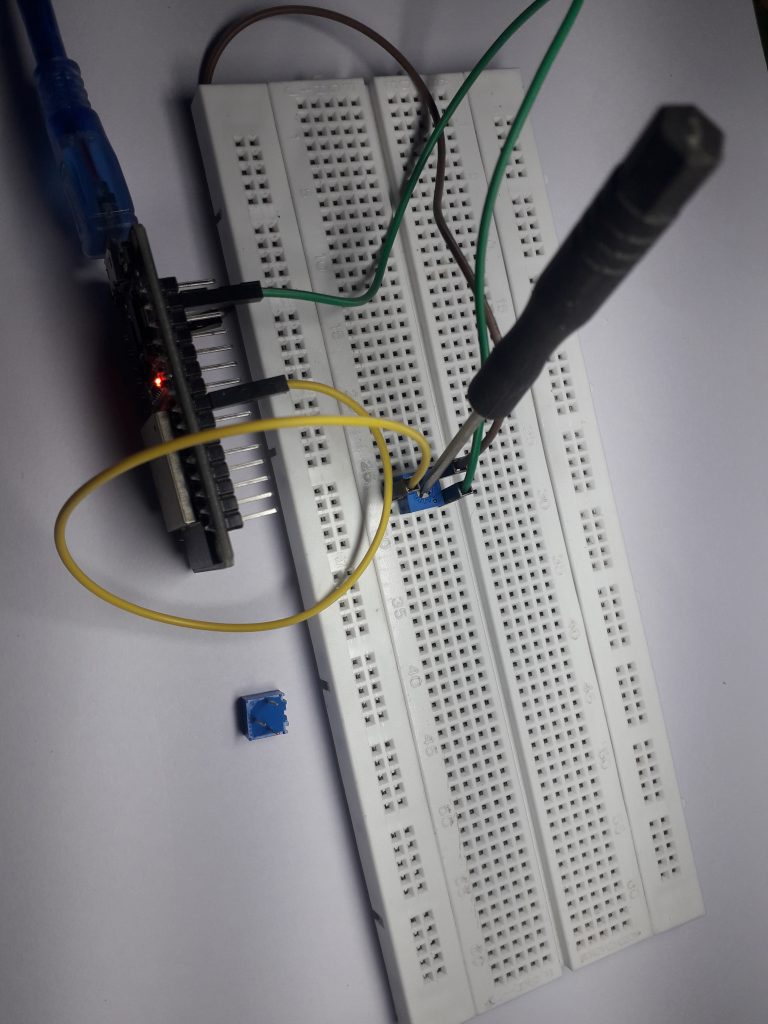
A variable resistor or potential meter is a device that varies the resistance of a material when a current pass through it
A variable resistor will have three pins( one front pin and two back pins)
First, insert the variable resistor into the breadboard
Second, connect the front single pin of the variable resistor to the esp32 pin25
Third, connect the GND pin of the esp32 board to one of the two-pin then the connect remaining back pin to the esp32 board with a 3V3 pin
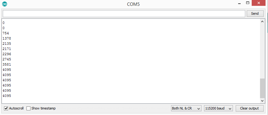
Fourth, open the serial monitor or serial plotter and rotate the variable resistor key to see the variation of voltage from 0v(0) to 3.3v(4095)
// Variable resistor  is connected to pin 25
const int resistor_Pin = 25;
// variable for storing the Variable resistor value
int resistor_Value = 0;
void setup() {
  Serial.begin(115200);
  delay(1000);
}
void loop() {
  // Reading Variable resistor value
  resistor_Value = analogRead(resistor_Pin);
  Serial.println(resistor_Value);
  delay(500);
}
Esp32 internal touch sensor
Let us see an example to use internal touch sensor of esp32
First, open file—->examples—–>ESP32—–> Touch——>Touch Read
void setup()
{
Serial.begin(115200);
delay(1000); // give me time to bring up serial monitor
}
void loop()
{
Serial.println(touchRead(T0)); // use D4 pin
delay(1000);
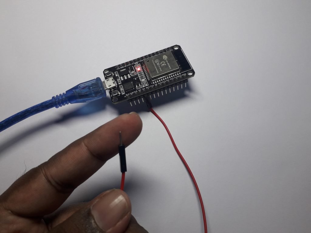
}To use the above code, take a jumper wire of male to female and connect to PIN D4 of esp32-board
Touch the metal part of the jumper wire to see the variation in reading and to see the output reading you use a serial plotter or serial monitor
Tool —-> serial plotter
Use jumper wire as switch
Let us see, how we can use a jumper wire as a switch to turn on and off a LED
use three jumper wires of male to female
first, connect the D25 pin of esp32 to the positive(+) side of the LED
second, connect the GND pin of esp32 to the GND of a breadboard
third, connect the D4 pin and touch the metal part of the jumper wire to turn on and off the led
finally, open the serial monitor to view led on and off
const int ledPin = 25;
const int SET_VALUE =50;
int touchvalue;
void setup() {
  // initialize digital ledPin as an output.
  pinMode(ledPin, OUTPUT);
   Serial.begin(115200);
  delay(1000);
}
// the loop function runs over and over again forever
void loop() {
  touchvalue = touchRead(T0);
  Serial.println(touchvalue);  // use D4 pin
  if(touchvalue < SET_VALUE){
    digitalWrite(ledPin, HIGH); // turn the LED on (HIGH is the voltage level)
    Serial.println(" - LED ON");
  }
  else{
    digitalWrite(ledPin,LOW);   // turn the LED off by making the voltage LOW
    Serial.println("- LED OFF");
  }
  delay(1000); // wait for a second
}
Pulse width modulation technique
By using the pulse width modulation technique we can reduce the intensity or brightness of the led similarly with this technique we can also control the speed of the DC motor
Esp32 board won’t support analogWrite( ) function but we can use the below script for Arduino Uno, due, mega
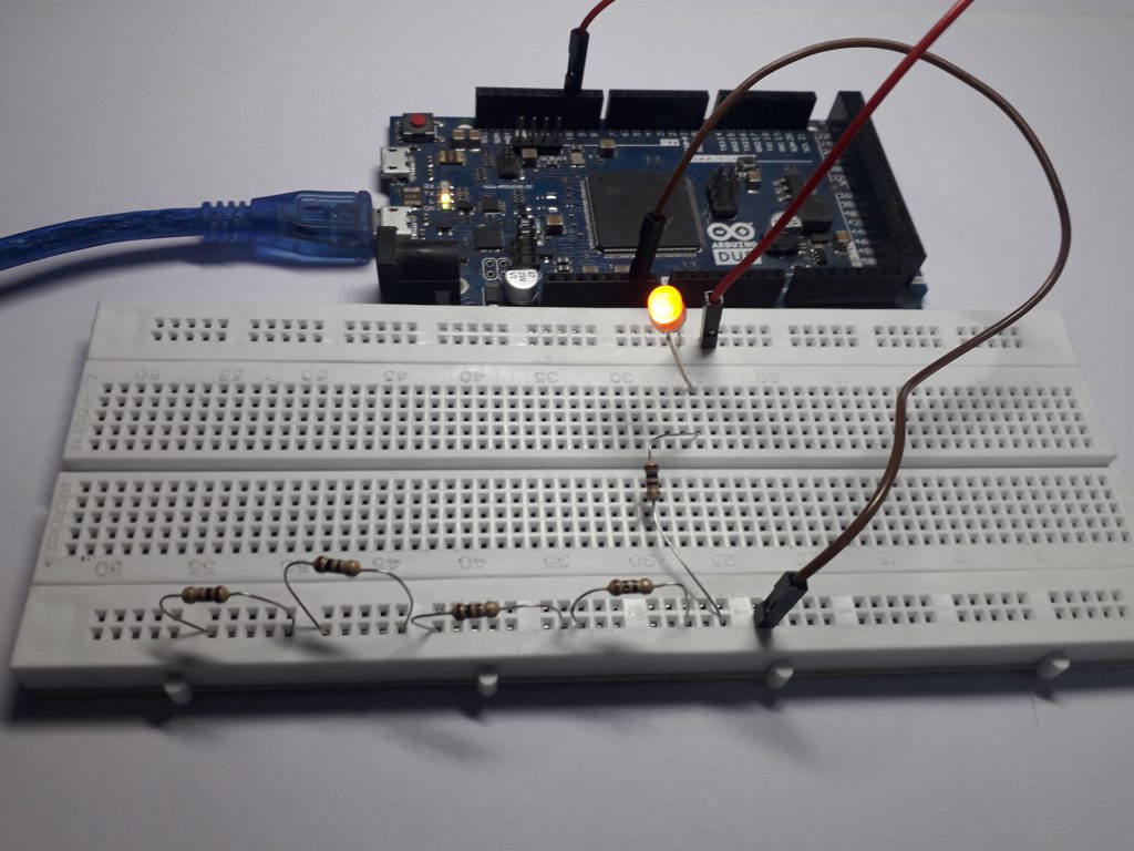
If you are using arduino due or uno or mega or any other arduino board you can test the below script to dim the led
- Take two jumper wires of male to male pin
- Connect pin 10 of arduino due board or any other arduino board to the positive(+) side of the led with a jumper wire
- Connect GND pin of Arduino board to the GND of a breadboard
int led_pin = 10;
void setup() {
  //Declaring LED pin as output
  pinMode(led_pin, OUTPUT);
   Serial.begin(115200);
  delay(10000);
}
void loop() {
  //Fading the LED
 for(int i=0; i<255; i++){
   analogWrite(led_pin, i);
   Serial.println(i);
    delay(5);
  }
  for(int i=255; i>0; i--){
    analogWrite(led_pin, i);
   delay(5);
  }
}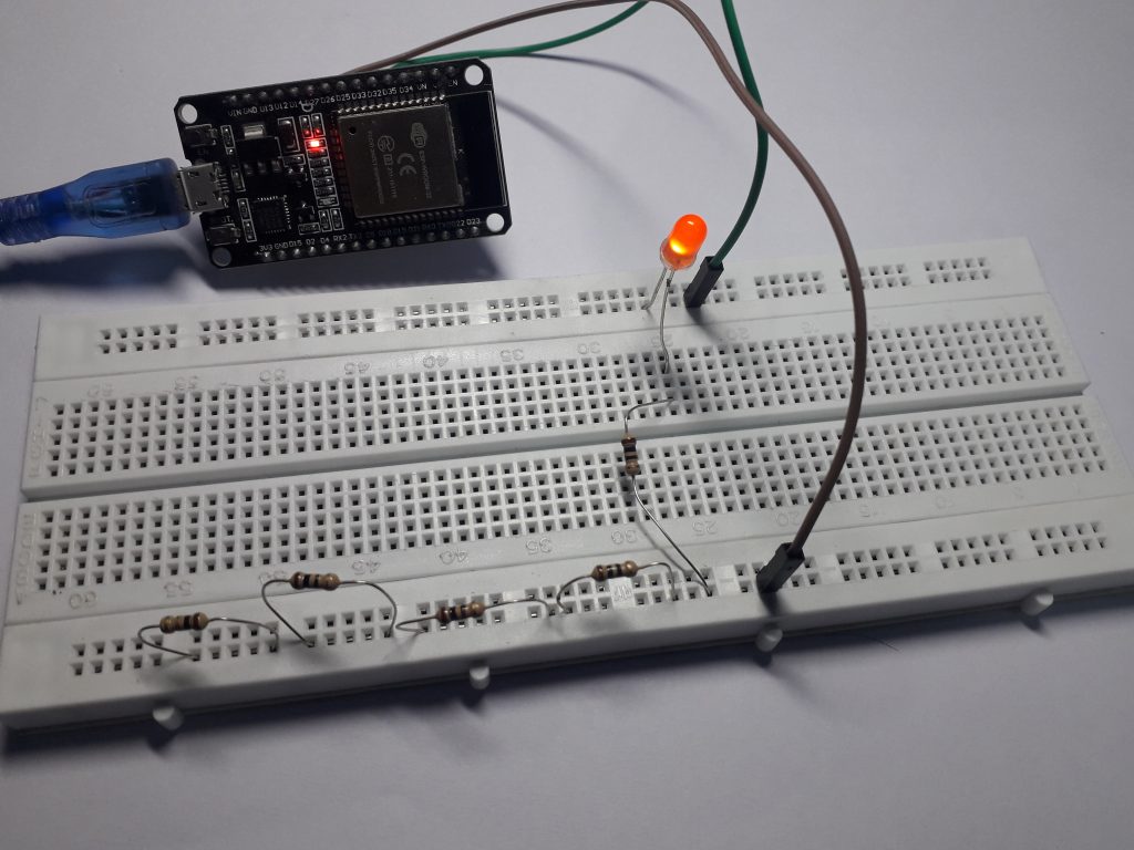
For the esp32 board, use the below script because we know that the analogWrite( ) function won’t have any support in esp32
- Take two jumper wires of male to the female pin
- Connect pin D25 of esp32 board to the positive(+) side of the led with a jumper wire
- Connect GND pin of esp32 board to the GND of a breadboard
const int ledPin = 25;
const int freq=5000;
const int ledchannel=0;
const int resolution =8;
void setup(){
ledcSetup(ledchannel, freq, resolution);
ledcAttachPin(ledPin, ledchannel);
Serial.begin(115200);
delay(10000);
}
void loop(){
for(int dutycycle=0; dutycycle<=255; dutycycle++){
ledcWrite(ledchannel, dutycycle);
Serial.println(dutycycle);
delay(15);
}
for(int dutycycle=255; dutycycle>=0; dutycycle--){
ledcWrite(ledchannel, dutycycle);
//Serial.println(dutycycle);
delay(15);
}
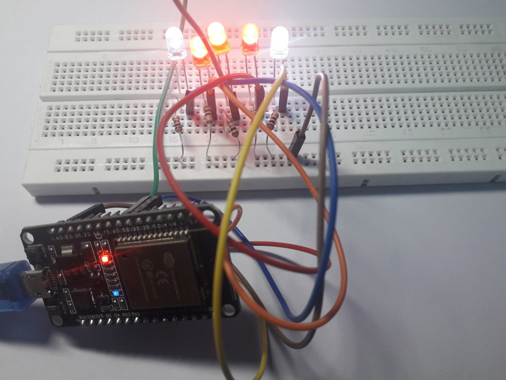
}Dim the 5 LEDs
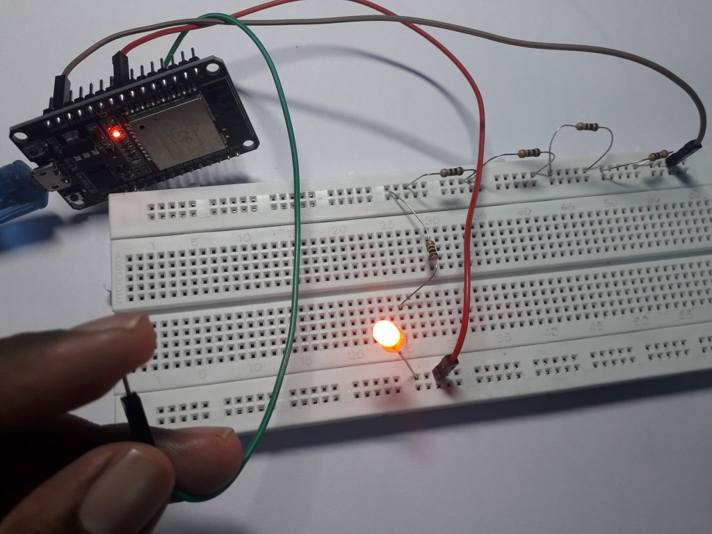
Let us, dim 5 LEDs with the same PWD technique
- First, take 6 jumper wires of male to female, 5 LEDs, 5 resistors of 330 ohm
- Second, connect the GND pin of esp32 to the GND of the breadboard
- Third, place the resistors in serial order by keeping in mind the positive(+) pin
- Fourth, connect all the resistors from the GND of the breadboard to the positive(-) pins of the LEDs
- Fifth,connect the esp32 pins 25,2,33,4,5 to the positive(+) pins of the led
const int ledPin = 25;
const int ledPin1 = 2;
const int ledPin2 = 33;
const int ledPin3 = 4;
const int ledPin4 = 5;
const int freq=5000;
const int ledchannel=0;
const int resolution =8;
void setup(){
  ledcSetup(ledchannel, freq, resolution);
  ledcAttachPin(ledPin, ledchannel);
  ledcAttachPin(ledPin1, ledchannel);
  ledcAttachPin(ledPin2, ledchannel);
   ledcAttachPin(ledPin3, ledchannel);
    ledcAttachPin(ledPin4, ledchannel);
   Serial.begin(115200);
  delay(10000);
}
void loop(){
  for(int dutycycle=0; dutycycle<=255; dutycycle++){
    ledcWrite(ledchannel, dutycycle);
    Serial.println(dutycycle);
    delay(15);
  }
  for(int dutycycle=255; dutycycle>=0; dutycycle--){
    ledcWrite(ledchannel, dutycycle);
    //Serial.println(dutycycle);
    delay(15);
  }
}
Leave a Reply