
L2 routing is done on layer 2 of the TCP/IP stack and the layer 2 of the TCP/IP stack is a called a data link layer
For L2 routing, only Mac addresses were used to deliver the packet to the destination, and IP addresses won’t play any role in L2 routing also L2 routing can be done only within a subnet
How does a packet get framed in TCP/IP stack
As you can see from the below table, on the right-hand side of the table we have a TCP/IP stack and on the other side, we have corresponding to each layer of stack most famous protocols are mentioned
| Packet header | TCP/IP stack |
| Application header http | Application layer |
| UDT/TCP header (port no) | Transport layer |
| IPV4/IPV6 header (protocol) | Network layer |
| Ethernet header (type) | Data link layer |
| Physical link layer |
Don’t get scared with the term “protocol”, protocol means a set of rules
- Ethernet is a data link layer protocol
- IPV4/IPV6 are network layer protocols
- UDP/TCP are transport layer protocols
- HTTP is an application layer protocol
As you can see that every layer of the TCP/IP stack have one piece of information is available in all the headers, that contain information regarding the protocol which is operating in the next layer of the TCP/IP stack
So, the Ethernet header have a field called type, the value of this type field helps us to know, the next layer protocol on which the network layer is operating
Is it IPV4 or IPV6 protocol?
For example: if the value of the type field is 0800 it means that the protocol that is operating in the network layer is the IPV4 protocol
If the value of the type is 041 then the protocol that is operating in the network layer is the IPV6 protocol
Similarly, in the network layer header, there is a field called protocol field, the value of this protocol field determines the transport layer protocol on which it is operating
If the value of the protocol is 6 then it means that the transport layer protocol is TCP protocol and if the value of the protocol is 17 then it means that the transport layer is operating with UDP protocol
UDP/TCP header contains a field called port no using this port no the operating system will identify the application which interested in receiving a particular type of packet
For example, consider an app1 at the application layer of TCP/IP stack and this application is listening on port no say 80 then if the packet arrive on the machine with port no 80 at this instant, the operating system will know that it needs to be delivered the packet to the app1
Ethernet header format

The above figure shows the Ethernet header format where
- The first 8 bytes are the preamble
- The field destination address is a 6-byte destination mac address
- The field source address is a 6-byte source mac address
- The type field is a 2-byte, which helps to identify the next layer of the protocol
For example: if the type field =0800 then the next header is ipv4 header
If the type field =0041 then the next header is ipv6 header
- Info field the min value of payload is 45 and max value of payload is 1500 bytes
- FCS field is a 4-byte checksum that helps to identify whether the received packet is corrupted or not
What could be the minimum size of an Ethernet frame
8+6+6+2+46+4=72 bytes
If we neglect the preamble then it will be 64 bytes
What could be the maximum size of an Ethernet frame
MTU=8+6+6+2+1500+4 =1526 bytes
If we neglect the preamble then it will be 1518 bytes
MTU stands for maximum transferable unit
How layer2 routing is done?
Do you know? How exactly the L2 routing happens? If you don’t know then let me explain to you how it happens?
L2 routing will happen only when one machine to another machine falls within a subnet

The above topology, shows an L3 router and on the right-hand side of the L3 router a subnet A is there, which have a network id as 12.1.1.0/24, and the subnet A contains four devices A, B, C, and L3 router
Suppose, machine B would like to send data to machine A so, then we can say that machine B will be a source machine while machine A will be a destination machine
Here are the steps that the L2 router will take to communicate
Step 1: B prepares the packet by making Ethernet hdr as SRC Mac =MB, DST Mac= MA, and TYPE =0800(IPV4)
Step2: machine B will transmit the packet on a wire at this instant, the packet will be received by all other remaining machines, that are connected to the wire (A, B, C, L3 router as well)
Step3: when other machines receive the packet
First: they will check whether DST Mac =Mac of receiving interface if it equals to their address then they will accept the packet
Here, accept the packet means they chop off the Ethernet hdr and handover the remaining to the network layer
Second: if DST Mac is not equal to Mac of receiving interface then it will discard the packet
As you can see, the only machine A accepts the packet, and the remaining machines C, L3 router will reject it
Why?
because the DST Mac address of the packet is not equal to the mac address of machines C and l3 router
So, this is how L2 routing is done purely based on Mac address
how the machine B will know the mac address of machine A?
Machine B knows the Mac address of machine A with the help of ARP (Address Resolution protocol)
What about machine C, which will get unnecessary disturbed for the packet which is not destined to it (thrashing)?
L2 switch solves the problem of thrashing
Demo of creating a custom topology by using python
Let us write a python program to build a Mininet custom network topology to demonstrate the L2 routing concept

The above topology shows an L2 switch S5 with host machine h1 which have a loopback IP address 122.1.1.1/32 and host machine h2 which have a loopback IP address 122.1.1.2/32
Both the host machines h1 and h2 are present in the same subnet and the interface h1-etho is configured with IP address 10.0.10.1/24 then the interface o h2-eth1 is configured with IP address 10.0.10.2/24
The interfaces of the L2 switch are S5 etho and S5 eth1 and we need to use these interfaces into some Vlan so, to demonstrate we say Vlan10 and both the interfaces of the L2 switch is configured with Vlan 10 in access mode
To build the custom network topology, we will use the Mininet tool and compile the python program on it
Why we used Mininet?
- Mininet can create a virtual network with nodes, links, switches and also allow you to do experiments
- Allow SDN(software-defined networking) development on any laptop
- Inexpensive
- Mininet has an extensible python APIs for network creation
So, if you don’t know, what is Mininet? How to install it? How to compile a python program on Mininet? What are the basic commands in Mininet? However, if you would like to know the answers to these questions then you need to read the blogs mentioned below
Python script
# Mininet Python APIs
#network emulation
from mininet.net import Mininet
#Simple command-line interface to talk to nodes
from mininet.cli import CLI
#virtual Ethernet, link emulator
from mininet.link import Link
if '__main__' == __name__:
    network = Mininet()
    # Add Hosts
    h1 = network.addHost('h1')
    h2 = network.addHost('h2')
    #Add L2 Switch s5
    s5 = network.addHost('s5')
    # add links to the switch S5
    Link(h1, s5)
    Link(h2, s5)

    # build the network topology
    network.build()
    # Remove default IP addresses from host's interfaces
    h1.cmd("ifconfig h1-eth0 0")
    h2.cmd("ifconfig h2-eth0 0")
    # Remove default IP addresses from Switch's Interfaces.
    # Switch Interfaces do not contain any IP addresses anyway
    s5.cmd("ifconfig s5-eth0 0")
    s5.cmd("ifconfig s5-eth1 0")
    # Create a vlan 10 on Switch s5
    s5.cmd("brctl addbr vlan10")
    # Bring up the Vlan interfaces on L2 switch up
    s5.cmd("ifconfig vlan10 up")
    # Add s5-eth0 to vlan 10 on L2 siwtch in Access mode
    s5.cmd("brctl addif vlan10 s5-eth0")
    # Add s5-eth1 to vlan 10 on L2 siwtch in Access mode
    s5.cmd("brctl addif vlan10 s5-eth1")

    # Assign IP Address to Hosts as ususal
    h1.cmd("ifconfig h1-eth0 10.0.10.1 netmask 255.255.255.0")
    h2.cmd("ifconfig h2-eth0 10.0.10.2 netmask 255.255.255.0")
    h1.cmd("ip route add default via 10.0.10.254 dev h1-eth0")
    h2.cmd("ip route add default via 10.0.10.254 dev h2-eth0")

    # Start Mininet Cli prompt
    CLI(network)

    #stop emulator
    network.stop()
Line 1 to 7: import API packages to write python programs in Mininet
Line 9: if ‘__main__’ == __name__: is a python function where the execution of python program starts
Line 11: network =mininet () creates a network instance, where the network instance is called by Mininet () constructor and network is variable
Line 15 to 16: as you can see, from the above topology that we have two hosts h1 and h2 so, we should add the two hosts to the topology
Line 18: add L2 switch to the network topology
Therefore, we have added all three devices from the above topology
Line 21 to 22: add the links and the names of the links will be automatically generated by Mininet in the order of etho, eth1, eth2, such as h1-(h1-etho)…….. (S5-etho) –S5
As you can see, we have not configured any interface to the hosting machines at the same time, we have not configured the loopback address and also we have not configured Vlan to the interface of the switch
Line 28 to 29: first remove the default IP addresses from host interfaces
Line 33 to 34: second remove the default IP address from the switch interface
To use brctl, install the bridge-utils package by using the below command
sudo apt-get install bridge-utilsCompile the python script
First, create a file to write a python script
cat>demo.pyType the python script, then save and exit the file by a short key ctrl+d
Compile the python script
sudo python demo.pyCheck the build network topology
As we have, built the above topology in Mininet then we check it by using the below commands
View the number of nodes in the topology
nodes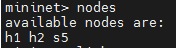
Shows even more information
dump
View the connectivity b/w nodes of the topology
net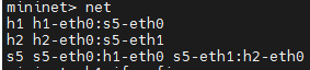
Check the interfaces of the host machine h1
h1 ifconfig -a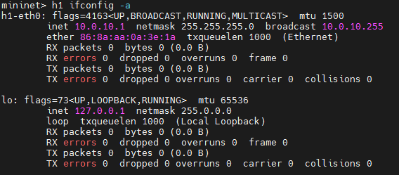
Similarly, you can also check the interfaces of host machine h2 but you need to replace the word h1 with h2 in the command
Next, you can ping host machine h1 to host machine h2 and also h2 to h1 because there is a link between them
h1 ping h2
h2 ping h1You can exit the ping mode by a short key ctrl+c
Check the routing table of host machine h1
h1 route -n
Similarly, you can see the arp table of host machine h1
h1 arp -n
Leave a Reply